Sound advice - blog

Tales from the homeworld

My current feeds

Mon, 2008-Jun-09

Delta Encoding in HTTP

So I have a document at a given URL, say "https://example.com/doc". It's a big document, and clients need a consistent synchronised replica of this document. The problem is that this document changes frequently, but only in small ways. It make sense that a client will have to grab a copy of the whole document initially, but do they really need to grab the whole document over and over as it changes? What options exist? Is "Delta Encoding in HTTP" the right answer, or is something else needed?

Straight HTTP

Let's start with the HTTP/1.1 of rfc2616. This protocol lets us go and fetch the data initially. Along with that fetch we might get an ETag, a Last-Modified, and/or explicit cache control mechanisms. These let us avoid transferring the document again if it has not changed. If it has changed, however, we must acquire the whole thing again.

Delta Encoding in HTTP

rfc3229 introduces "Delta encoding". This allows us to make a request that says: "Hey, I have the representation with this ETag already. Can you give me the diff against my document to catch up to the current representation?". It looks a little like this:

GET https://example.com/doc HTTP/1.1
If-None-Match: "123xyz"
A-IM: diffe

This says that the client is willing to accept a patch in "diff -e" format from the server. The client can apply this patch against the document it already has to update it to the current revision. A special 226 IM Used response indicates that the sever has understood the request and knows what to do with it.

The general idea would be that the server keeps either copies or diffs relating to several recent versions of a representation. At request time the server will combine recent diffs into an update that brings the client up to date from its current ETag. If it happens to ask for an ETag that is too old, it will simply get the whole document back again.

The model is still nicely stateless. Any number of clients might sitting on the same Etag-identified document version. The server doesn't try to track individual clients, so should be able to handle a serious number of them. The server's only important decision is how long to make the queue. This could relate to a fixed amount of available storage space, a fixed number of document revisions, a fixed time range, an unbounded revision control history with manual purging, or even perhaps some dynamic behaviour based on requests made to date. Interestingly, I suppose, only revisions that were actually transmitted to someone need to appear in the list of diffs.

The delta encoding RFC is a proposed standard, but seems to have a number of problems in this usage profile:

So what's the alternative?

Multi-URL approach

The two basic approaches here are a one-URL solution or an "n"-URL solution. rfc 3229 uses a one-URL approach, where different diffs are returned to different clients from the main resource URL. An "n"-URL solution would give a unique URL to each diff. Adding URLs seems to be the answer to most problems in the REST domain, so let's have a go at applying it to this one.

The first request

The first request is always going to return the whole document. Instead of simply returning an ETag, consider the possibility that a response will contain a hyperlink. This hyperlink would be to the document that will become the diff against this revision of the resource to update it to the "current" revision at that time. An example response:

HTTP/1.1 200 OK
Link: <https://example.com/doc/deltas?last=123xyz>; rel="Deltas"
Content-Type: ...
...

This rel-deltas link might tell an aware client that it can acquire deltas against the current version by querying the listed URL. The client may use this URL for the second request, below. An Etag and other cache control information may also be included for non-delta-aware clients.

The second request

When the client suspects that the resource has changed it will issue a GET request to the Deltas URL. It will specify the patch formats it understands as mime types in an Accept header, and otherwise the request will be as normal:

GET https://example.com/doc/deltas?last=123xyz HTTP/1.1
Accept: ...
...

The response that comes back might depend on whether changes have occured, and on whether the delta can be generated. The normal delta case:

HTTP/1.1 200 OK
Link: <https://example.com/doc/deltas?last=456abc>; rel="Next"
Content-Type: ...
...

This would deliver the delta to the client in a format the client understands. Normal content negotiation and other features of GET are employed and various kinds of errors can be reported. Some errors would leave the client in the dark as to how it should proceed, and the client would fall back to fetching from the main URL again.

The "Next" link is important. We can't have a client that has successfully applied this delta to ask for its delta from the same place again. Other clients may need this URL, and the client needs to move on to another. In this case the client should move onto the "next" delta in the series for its next request.

Here we see the case where nothing has changed, yet:

HTTP/1.1 204 No Content

Nice and easy. Nothing has changed, so nothing to see here. Cache controls are likely to be the same as for the main URL, but might differ. The client should try again next time it suspects something might have changed.

Finally, we have the case where the delta we are trying to fetch is too old:

HTTP/1.1 410 Gone

Gone is appropriate here, as this URL is no longer expected to work for anyone. However, clients must also be ready to treat a generic 404 Not Found in the same way. The client would be expected to fall back to querying the main URL, restarting the state synchronisation from a current state.

Subsequent Requests

Subsequent requests would hop from next to next as required by the client, and as the client anticipates a change may have occurred.

There is actually a fairly deep question in this approach as to whether the client should follow a Delta or Next link immediately or not. The answer is potentially tied up in caching.

We theoretically want caches to work well with this approach. Now, caches might be smart enough to apply patches themselves and feed them downstream. On the other hand, we might be dealing with caches that are deployed today. Rather than treating the caches as smart relays, we could potentially treat them as "dumb" independent relays for main URL and delta URL responses.

The fact that we want the caches to work for us means that we don't want to set no-cache directives on delta URLs. The data retrieved by any given client may therefore be out of date when it arrives, within freshness criteria attached to the delta. This criteria will either cause the cache to refetch, revalidate, or return data without revalidating. This information is combined with client preferences to determine whether the client is actually returned the freshest possible data or not.

However we do this, I think we can trust the existing caching models for dealing with deltas. Whenever we are given a delta URL the assumption should be that until proven otherwise there is no data there. If the caching model on the data that supplied the new delta URL says that data can be a few seconds out of date, the link will also be a few seconds out of date. If the model says we must revalidate, we'll get something more up to date.

Conclusion

Some advantages to the alternative approach include:

I am fast forming the view that a few links in HTTP headers will be more effective than an implementation of 3229. I think this approach avoids complication at proxies, avoids introduction of new return codes and headers, and will be more generally applicable. For example, it could be used to cheaply transmit new atom feed entries to clients who aren't quite up to date rather than just keep a large document in sync.

Benjamin

Sun, 2008-Jun-08

4+1 View Scenarios, and the rest

This is the final chapter in a series I have been running on my evolving understanding of 4+1 view architectural descriptions. This time around I am covering scenarios, and other things that might end up in an architectural description. We have already established the set of components in our architecture, and the functional interfaces to external systems. We have drawn links between components, but not really elaborated on where responsibilities lie between a given pairing of linked components.

Scenarios

The scenarios view seems to be the most flexible of the views, and seems to capture "other". I think I am sticking fairly closely to the Architectural Blueprints definition when I use this view primarily to convey behaviours of components and internal interfaces. I have been using collaboration diagrams showing component interactions in arrangements that roughly correlate to the Process View presentation. As with other views I have generally tried to align things to the Logical View classification, and attempted to come up with one or more scenarios for each logical function.

Sales Scenario: Record Sale

Recording of sales is a fairly straightforward transfer of Sales Records from Web Browser to the Sales Manager Component. Financial Transactions pertaining to these records are submitted to the General Ledger for further analysis.

It is possible that we could talk more about the user interface than I have in this diagram. We could talk about how the browser navigates to the page that lets them enter the Sales Records. I have deliberately kept things fairly simple here, trying to focus on clarifying roles within the architecture rather than getting too tied up in the detail of various interfaces involved. Even my method invocations don't look right from a UML perspective. They are really more along the lines of data flows, and I don't expect a literal analogue to exist for any of these method invocations.

Another way to approach the Scenarios View would be to take things back up a notch. Use cases may better capture the end user's intent, whether they be UML-style use cases or more general Systems Engineering -style use cases. I think there is a lot of flexibility in this area, which makes things difficult to nail down. I share the experience of how I have been approaching my specific problem domain, and hope that it leads to some useful light-bulbs going off in someone else's head.

Inventory Scenario: Stocktake

The Stocktake scenario is instructive because it tells us that Inventory Manager is directly involved in the stocktake procedure. It is not an idle bystander that accepts a bulk update at the end of the stocktake. The Stocktake GUI starts the process by marking all stock as outstanding. One by one items are ticked off from the list until the remainder must be considered shrinkage. This means that only one stocktake can be going on at a time, and that the work of stocktake might be undone if someone starts the procedure again. On the other hand, it means that a crash in the stocktake GUI won't lose us our current stocktake state. Does this division of responsibility strike the right balance? That's what this design process is intended to make us ask ourselves.

Shares Scenario: Enter buy or sell

We decomposed the Shares function more than most others, and this gives us an opportunity to see how a diagram with many components might work. Note that I have more arrows now than I have labels against those arrows. I have been using a convention that continuing arrows carry the same data as the last one unless indicated otherwise. In this diagram we have the Buy or Sell Record moving about essentially untouched until it gets to General Ledger Export. Only then is it converted into a Financial Transaction for recording in the General Ledger.

I find it interesting to pinpoint components that have little to do with altering the content that passes through them. From a REST/web perspective we might apply the End to End principle here. Not only should the interim components not modify the data passing through them, they should generally not try to understand the data more than necessary either. If communication is in the form of documents, they should ignore but pass on attributes and elements even if they don't understand them. Take care to clean documents up at system boundaries in order to be able to assign blame, but otherwise try to keep things free and easy. Even the document clean-up should ideally be done by free standing document firewalls that are easy to reconfigure as the architecture evolves.

I haven't included all of the images this time around. If you would like to look at the whole (but still limited) set of diagrams I put together, point your StarUML here.

The Rest

Clearly 4+1 is not the whole story. There are levels of detail beyond what I have covered in my examples this time around, including interface control documentation and module design specifications. There are also a great deal of additional details that may accompany an architectural description to support design decisions made or to provide more detail.

Perhaps the most obvious gap in the 4+1 as applied at this level is a lack of data models for logical entities, for configuration data, and for interfaces. These data models can be extremely useful, and the earlier you have a stab at them the less likely you'll have multiple teams misunderstanding each other.

Other gaps include objectives for the decomposition, rationale for choices made, descriptions of how the architecture would change if current assumptions and constraints were to change, and a host of other detail. Any one of these could lead you down the path of discussing something to the point where you stop and say to yourself "Hang on. That doesn't make sense. What if...". Those moments are half the reason to put an architectural description together, and some of the value of the document can be measured in how many "oops"es are caught as compared to the effort you put into the document.

The other side of the document is obviously to steer the ship and record consensus decisions. Communicating the reasons for the current set of design decisions and the set of alternatives considered can therefore be crucial in the maintenance of the document over the project lifetime.

In the end, everything on the project is linked. From schedule to team structure to components to the list of change requests against those components. If you start modelling you might just end up modelling the whole world. Depending on the scale of the project it might be worth going that far. If you are working on something smaller you should be doing the minimum and assessing the rewards for taking any further steps with the document set.

Conclusion

I come from a fairly heavy-weight process end of the industry. It involves a Systems Engineering approach that has foundations in things like defense projects. The kinds of descriptions I have been talking about may not suit everyone, or perhaps even anyone. However, I hope they will make some of us take a step back and be aware of what we as a whole are building from time to time.

Again I am not an expert, and I hope my lack of expertise is not a hindrance or false signpost to the gentle reader. I am a software guy who has been walking a path lately between traditional software experience and the experience of those around me working on various projects.

I'll now return you to your usual programming of REST Architecture, and everything that goes with it.

Benjamin

Mon, 2008-Jun-02

The 4+1 Development and Deployment Views

This is part four of my amateur coverage of the . I left my coverage last time with the logical and process views complete. The logical view is a system's engineering coverage of the system's functional architecture. My Process View closed out most of the design aspects of the system. We now have a set of software components and functional interfaces which we may further refine.

The Development View and Deployment (Physical) view close out main set of views by moving software components out of their final assembled forms and into other contexts. The Development View captures components "in the factory". In other words, it shows build-time relationships between components. The Deployment View captures components being deployed to the operational system. If we were continue clockwise around the views through Development and Deployment we would naturally reach the Process View again. In other words, components once built and deployed are assembled into processes.

The Development View

The Development View is where I like to travel to in telling my architectural story, after the Process View. We have seen the final assembly of processes, now let's go back to where it all began. If your architecture has a strong distributed object focus this view will be relatively simple, but it does serve an important function.

The Development View is where we make a break from whole Logical Functions, and narrow ourselves down to their core for deployment. Let's follow our example through:

Development Packages

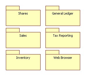
The packages view isn't very interesting. It would perhaps be more so if I had included actual database software or other basic components to get the job done. Those would very likely appear at this level, alongside packages we discovered in the Process View. There are no build-time relationships in this set, only run-time relationships.

Sales (Development View)

The Development View for Sales includes all the components that made up the Process View diagram of the same name. These components are everything that is required to put together the Logical View Sales function.

Something has changed, though. This time around our packages are in the diagram itself. We can see a Sales package, and it clearly doesn't contain all of the software components involved. When we deploy "Sales" it will be this core set of components (only one in this case) that will be deployed. The Sales Manager component will be deployed as part of General Ledger. The Web Browser will be deployed as part of its own package.

Inventory (Development View)

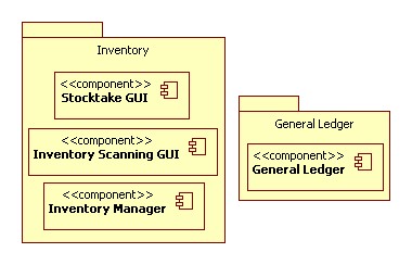
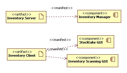
Inventory shows multiple components within a functional core. Inventory contains both its client- and server- side components.

Shares (Development View)

Shares shows that some of the run-time relationships found in the Process View are linked together at build-time. The Portfolio Manager controller component depends on and links together all of the other constituent parts.

Tax Reporting (Development View) Tax Reporting (Development View) Tax Reporting (Development View)

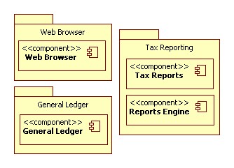
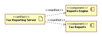
The remainder of these diagrams are fairly boring. However, they do ask us to consider what libraries or other components we might have missed in our Process View analysis. This will be important contributors to the final set of software components and may significantly influence planning and estimation on a large monolithic project.

The Deployment (Physical) View

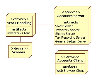
The Deployment View is about the final installation of components into the operational system. It is theoretically concerned both with the mapping of software components and processes to physical devices. However, again mine didn't quite turn out that way. I ended up focusing on packaging. Here is my top-level diagram:

Deployment (Physical) Packages

This image shows the physical structure of final Accounts system. We have a Stock Handling workstation with a Scanning device attached. It contains the thick inventory client.

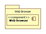
On the right we see a single Accounts server on which we plan to deploy the entire server workload. A generic client machine carries a Web Browser to render the various HMIs.

We are limited in what we can do with a UML deployment diagram like this. We obviously can't dive too far into the nature of the hardware components in what is really a software diagram. We can't draw the racks or get too far into the detail of the network architecture. These facets seem to fit outside of the 4+1 views.

Sales (Deployment View)

The Deployment View for Sales is significantly slimmed down from previous logical-aligned views. For the first time we see the non-core components such as the Web Browser stripped away and absent. What is left is a pure server-side component, so we put it in a package of that name and deploy it onto the Accounts Server class of machine.

Inventory (Deployment View)

Inventory is more interesting. We have a client and server side to this functional core. They must be deployed separately. Even at this late stage we can see potential holes in our design: Did we think about the client/server split? Can we see components that need extreme bandwidth or latency settings, and should be co-located?

Shares (Deployment View)

I haven't shown all the dependent components for Portfolio Manager under the Shares function core. I assume they are all included at build time and do not require special attention when it comes to this level of packaging.

Tax Reporting (Deployment View) General Ledger (Deployment View) Web Browser (Deployment View)

Again, the rest of these diagrams are pretty boring due to lack of intelligent detail.

Conclusion

That concludes the main four views. I hope this coverage has been useful, and expect to see a number of "no, this is the way it is done!" posts in response. My approach has not been entirely kosher, and is not based on a broad enough base of experience. However, it does what I set out for it to do. It identified a set of software components and functional interfaces. It aligned the set through multiple views to the end user's functional requirements. It examined the set from multiple angles to see how they would play out:

It did not decompose components or interfaces any more than necessary, hopefully making the necessary high level decisions without boxing individual component authors in unnecessarily.

This approach is suitable for architectures of size, both REST and non-REST. Again, it might surprise some that REST has not specifically appeared at this level.

The way I view it is that this is an approach to selecting components to build and identifying the demands on interfaces between them. Each component will still be built according to best practice and will conform to appropriate standards. If I were to build a circuit breaker for the electric power industry, or an impulse fan for environmental control, I would supply digital inputs and outputs of a standard type for connections to RTUs, PLCs, or other field devices. If I am to build a software component, I will supply URLs to allow it to be connected freely and generally also. I will follow industry best practice for loose coupling, maximum scalability, and maximum evolvability. These views told me what to build. REST tells me how to build it.

To some extent I want REST advocates to see this other side of things. Whether you do this formally or informally and by what ever technique: There is a process of deciding what to build and what interfaces are required in software engineering. There is an architecture role that is about the specifics of what is needed in a particular system. REST is a technique that informs this level of architecture, but is subservient to it. I sometimes wonder if this is the main reason for disconnect between the REST and SOA camps. One is talking about which components to build, while the other is talking about how to connect them together. Little wonder that we can't agree on how to do "it".

I plan to round out this series with a discussion of the Scenarios View, and about other supporting documentation that might be needed to support your architectural decisions.

Just a reminder: You can find the StarUML model I used in this example here.

Benjamin